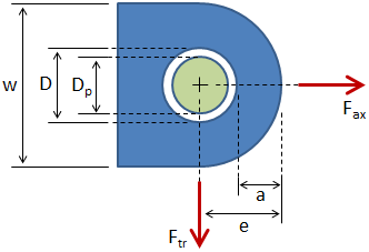

From the above dimensions, the effective edge distance is calculated: It should be noted that h 3 is defined as the smallest dimension on any radial section around the hole, but it will typically be equal to a. If the lug is symmetric, then the values for these dimensions can be easily obtained from the dimensions for an axially loaded lug: Where h 1, h 2, h 3, and h 4 are failure planes of interest. F bru.L and F bry.L are the lug ultimate and yield bearing stresses, respectively, and are given by the following equations:Į/D 5 then the lug is thin, and in that case the value of K is read off of the second plot below. Where D is the hole diameter, t is the lug thickness, and S tu and S ty are the lug material's ultimate and yield tensile strengths, respectively.

The ultimate bearing load, accounting for bearing, shear-out, and hoop tension, is given by: a = distance from edge of hole to edge of lug = e − 0.5 D.The figure below shows the lug in blue and the pin in green. In the simplified analysis, the following failure modes are considered:Ī factor of safety is calculated for each of the failure modes, and as long as each factor of safety is acceptable then the lug can be considered to pass. While it is relatively easy to perform, it only gives an approximate determination of the adequacy of the lug and should not be employed for critical structure. This method is based on first principles (as well as on the simplified method outlined in Bruhn) and involves making simplifying assumptions about the nature of the failure. This method is simpler than the Air Force Method, but it only allows for lugs under axial loading and does not account for the interaction between the lug and the clevis pin.Īll of these methods are described in the following sections. This method also accounts for the interaction between the lug and the clevis pin.ĪSME BTH - This method considers most of the failure modes above, and it uses simplified equations with correction factors based on empirical data to determine more accurate allowable loads. This method allows for lugs under axial loading, transverse loading, or oblique loading. This has the advantage of being relatively easy, but it only gives an approximate determination of the adequacy of the lug.Īir Force Method - This method considers most of the failure modes above, and it uses empirical curves to determine more accurate allowable loads. Simplified analysis - This method is based on first principles and involves making simplifying assumptions about the nature of the failure and calculating factors of safety. There are several common methods of analyzing a lug: Out of plane buckling ("dishing") - (not shown in the figure).Hoop tension failure / fracture on single plane.The numbers correspond with the labeled sections from the above figure: The failure modes for the lug are listed below.


 0 kommentar(er)
